 Lxshow
1 / 5
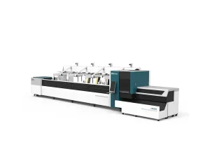
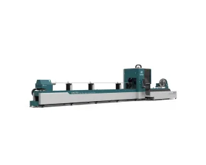
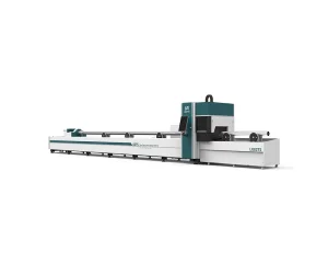
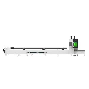
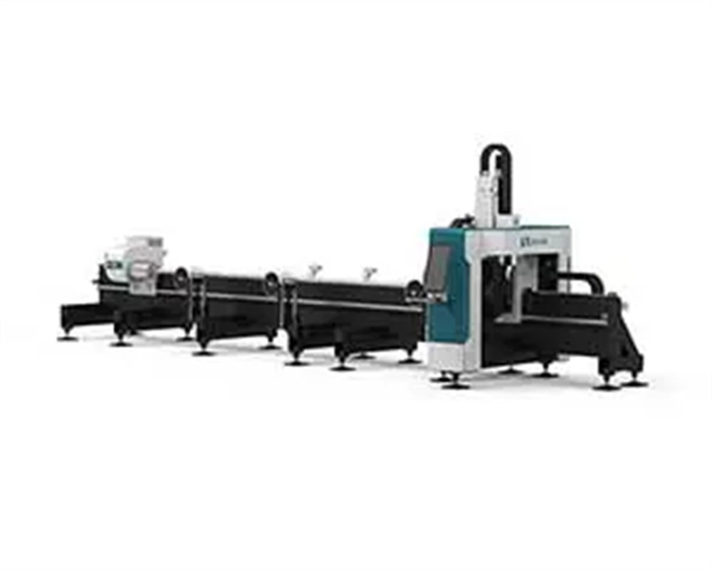
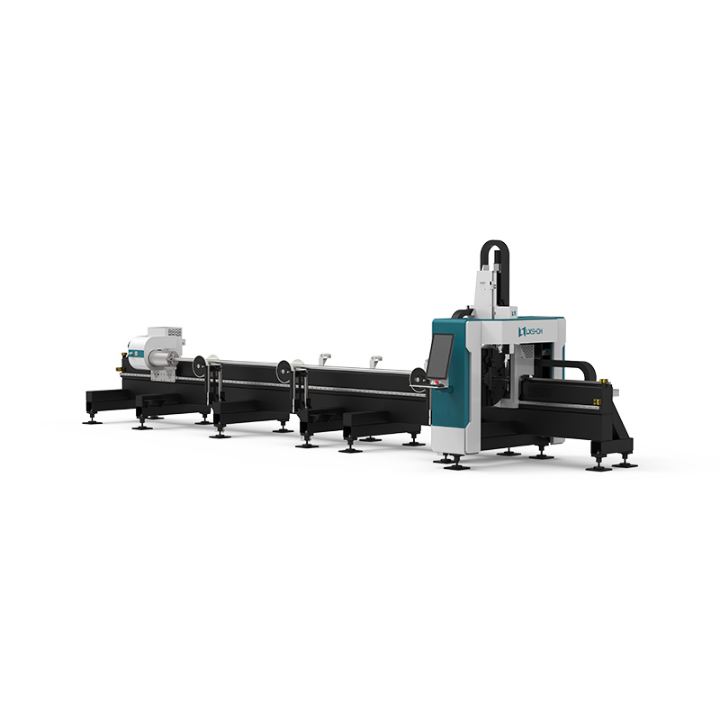
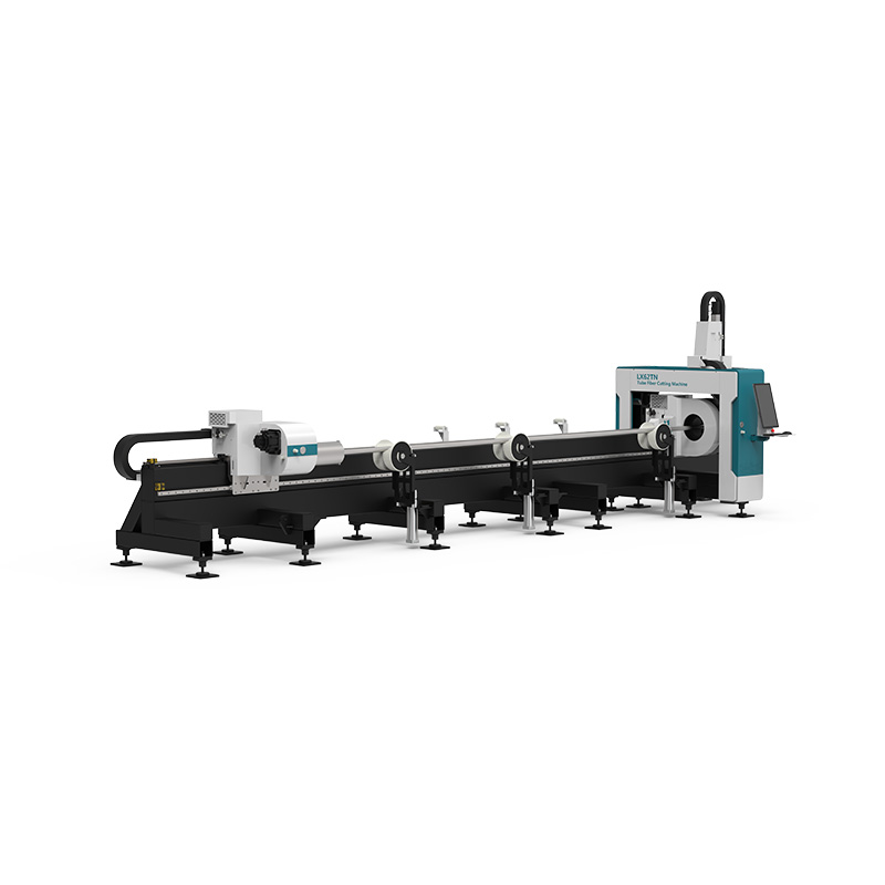
The bed adopts a side-hanging structure and a one-piece welded bed, which is annealed to eliminate internal stress. After rough machining, vibration aging is performed before finishing machining, thereby greatly improving the rigidity and stability of the machine tool and ensuring the accuracy of the machine tool.
The AC servo motor drive is controlled by the numerical control system, and the chuck realizes reciprocating motion in the Y direction after the motor drives, realizing rapid movement and feeding motion.
Both the Y-axis rack and linear guide rail are made of high-precision products, which effectively guarantee the accuracy of the transmission; the limit switches at both ends of the stroke are controlled, and a hard limit device is installed at the same time, which effectively ensures the safety of the machine tool movement; the machine tool is equipped with the automatic lubricating device adds lubricating oil to the moving parts of the bed at regular intervals to ensure that the moving parts run in good condition, which can improve the service life of guide rails, gears and racks.
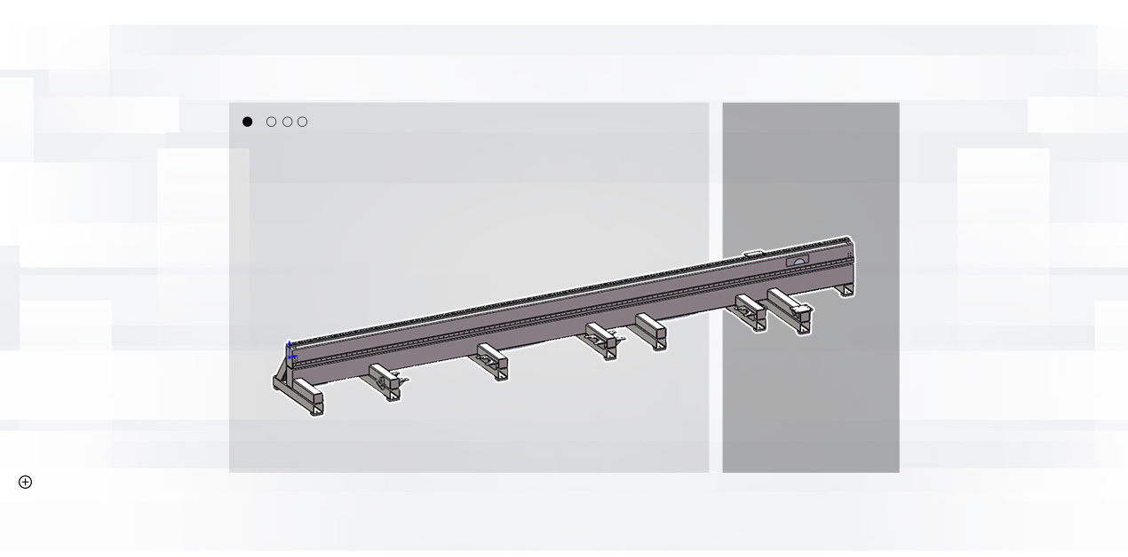
The front feeding device includes a support plate controlled by an air cylinder, which supports the pipe when the cut pipe is long and prevents it from sagging.
When the workpiece is being cut, the raised support cylinder supports the support plate to support the pipe and prevents it from sagging. When the workpiece is cut, the raised support cylinders are all retracted, and the workpiece falls to the blanking plate and slides to the storage place. The cylinder action is automatically controlled by the system.
The front section is also divided into follow-up type and manual adjustment type.
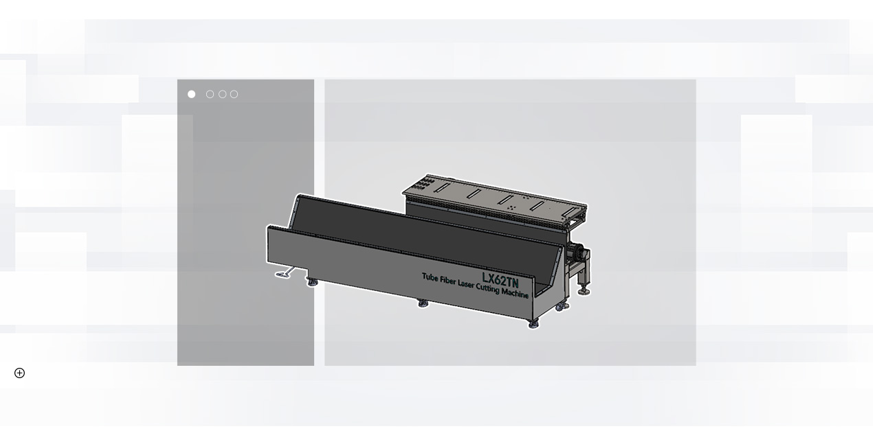
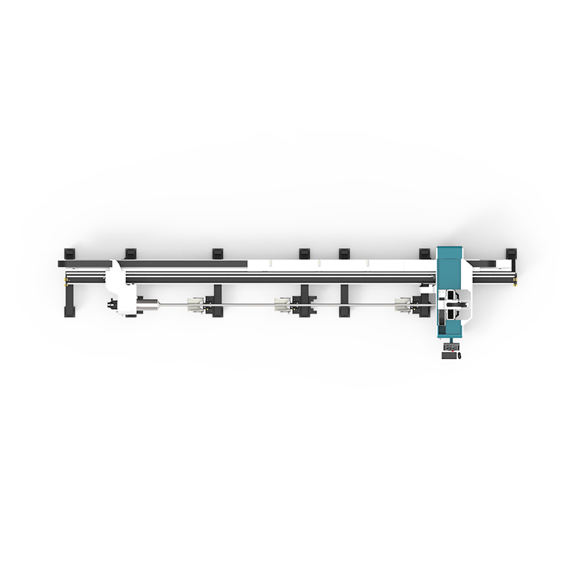
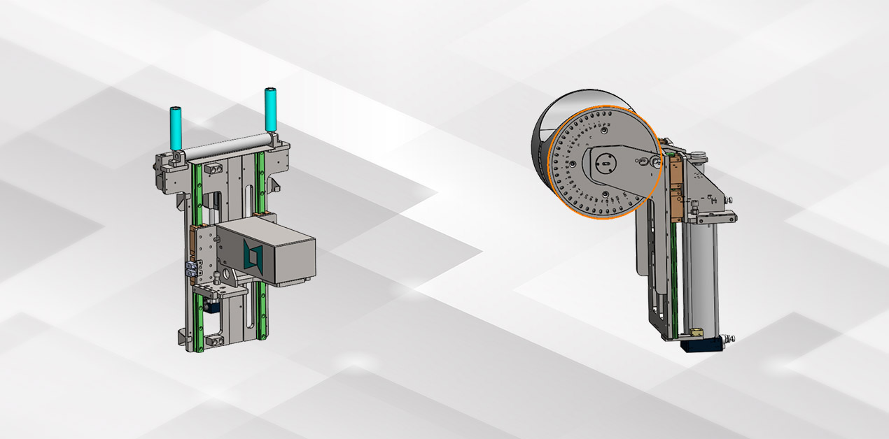
There are 2 sets of supporting mechanisms installed on the bed, and there are two types available:
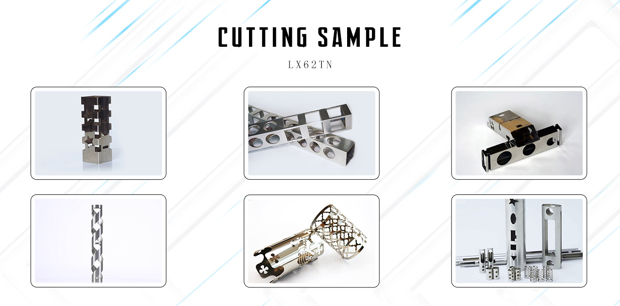
Fiber Laser Metal Cutting Machine is suitable for metal cutting like Stainless Steel Tube, Mild Steel Tube, Carbon Steel Tube, Alloy Steel Tube, Spring steel Tube, Iron Pipe, Galvanized Steel Tube, Aluminum Pipe, Copper Tube, Brass Tube, Bronze Pipe, Titanium Pipe, Metal Tube, Metal Pipe, etc.
Fiber Laser Cutting Machines are widely used in manufacture Billboard, Advertising, Signs, Signage, Metal Letters, LED Letters, Kitchen Ware, Advertising Letters, Tube Metal Processing, Metals Components and Parts, Ironware, Chassis, Racks & Cabinets Processing, Metal crafts, metal art ware, elevator panel cutting, hardware, auto parts, Glasses Frame, Electronic Parts, Nameplates, etc.
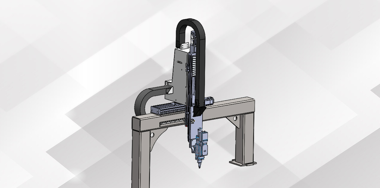
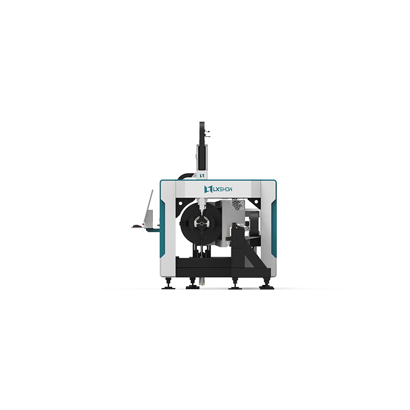
The crossbeam of the X-axis device adopts a gantry structure, which is welded by a combination of square tube and steel plate. The gantry component is fixed on the bed, and the X-axis is driven by a servo motor to drive the rack and pinion to realize the reciprocating motion of the slide plate in the X direction. In the process of movement, the limit switch controls the stroke to limit the position to ensure the safety of the system operation. At the same time, the X/Z axis has its own organ cover to protect the internal structure and achieve better protection and dust removal effects.
The Z-axis device mainly realizes the up and down movement of the laser head. The Z-axis can be used as a CNC axis to perform its own interpolation movement, and at the same time, it can be linked with the X and Y axes, and can also be switched to follow-up control to meet the needs of different situations.
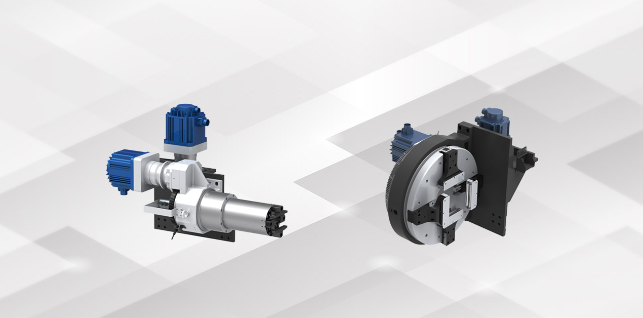
The chuck is divided into front and rear two pneumatic full-stroke chucks, both of which can move in the Y direction. The rear chuck is responsible for clamping and feeding the pipe, and the front chuck is installed at the end of the bed for clamping materials. The front and rear chucks are respectively driven by servo motors to achieve synchronous rotation. Under the joint clamping of double chucks, short tail cutting can be realized, and the short tail of the mouth can reach 20-40mm, while supporting the short tail cutting of longer tail.
The TN series pipe cutting machine adopts the method of chuck movement and avoidance, which can realize the cutting with two chucks all the time, and will not cause the pipe to be too long and unstable, and the precision is not enough.