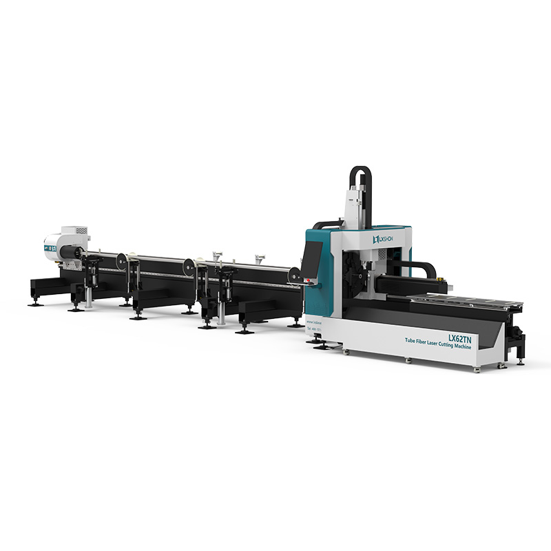
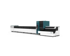
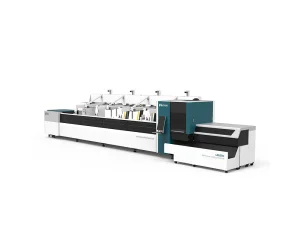
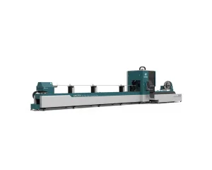
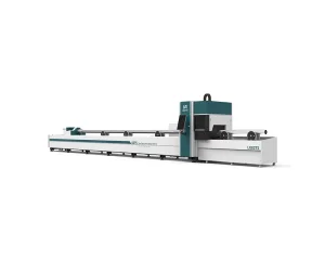
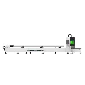
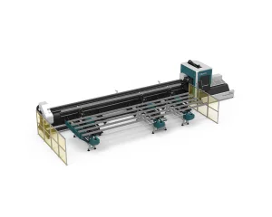
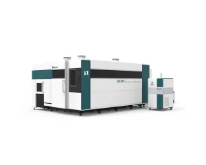
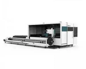
ODM 62TN Semi Automatic Feeding Metal Pipe Fiber Laser Cutting Machine Manufacturers, Exporters

Product Description

Heavy-Duty Machine Bed
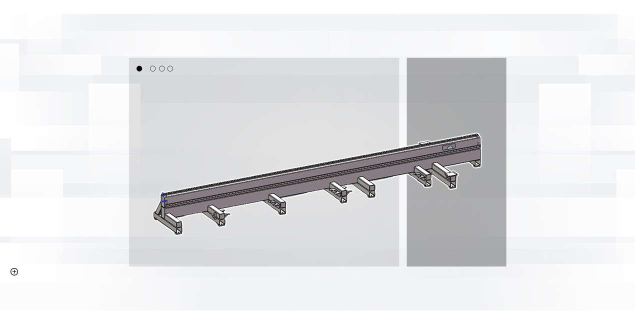
Machine Bed Structure
The bed adopts a side-hanging structure and a one-piece welded bed, which is annealed to eliminate internal stress. After rough machining, vibration aging is performed before finishing machining, thereby greatly improving the rigidity and stability of the machine tool and ensuring the accuracy of the machine tool. The AC servo motor drive is controlled by the numerical control system, and the chuck realizes reciprocating motion in the Y direction after the motor drives, realizing rapid movement and feeding motion. Both the Y-axis rack and linear guide rail are made of high-precision products, which effectively guarantee the accuracy of the transmission; the limit switches at both ends of the stroke are controlled, and a hard limit device is installed at the same time, which effectively ensures the safety of the machine tool movement; the machine tool is equipped with the automatic lubricating device adds lubricating oil to the moving parts of the bed at regular intervals to ensure that the moving parts run in good condition, which can improve the service life of guide rails, gears and racks.
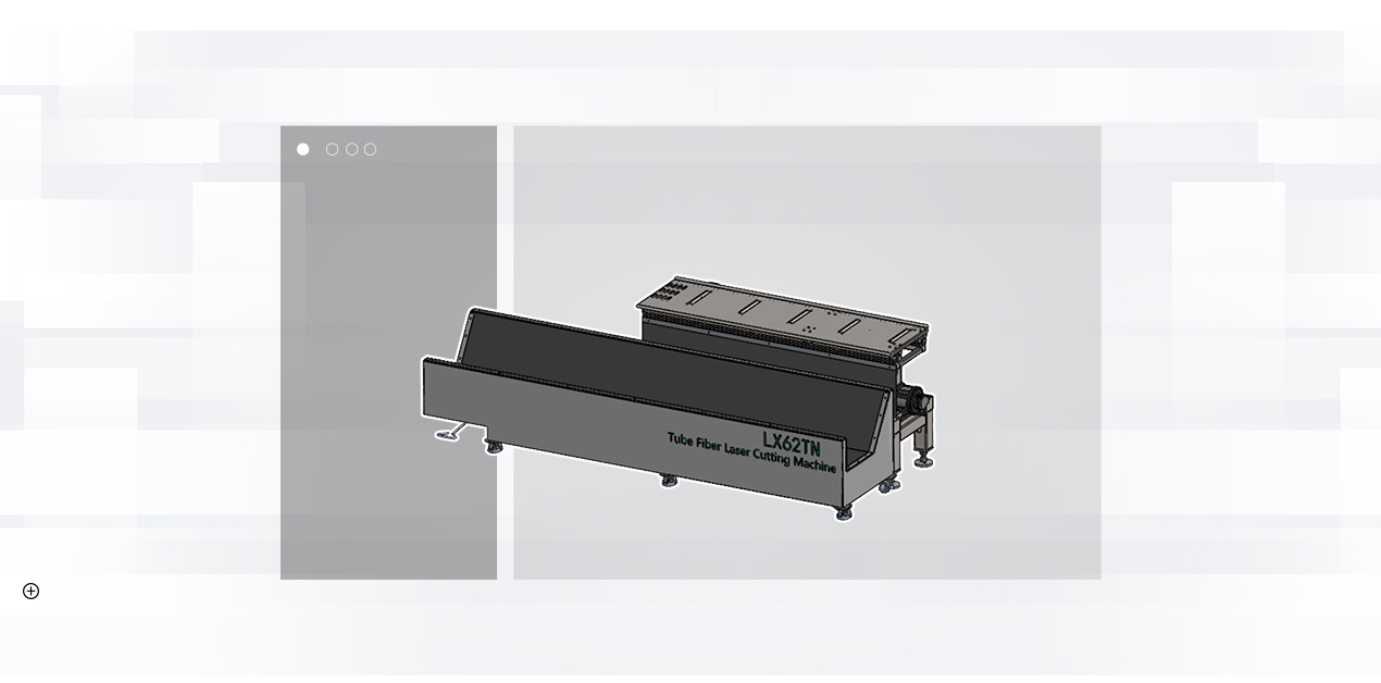
Front Feeding Device
The front feeding device includes a support plate controlled by an air cylinder, which supports the pipe when the cut pipe is long and prevents it from sagging. When the workpiece is being cut, the raised support cylinder supports the support plate to support the pipe and prevents it from sagging. When the workpiece is cut, the raised support cylinders are all retracted, and the workpiece falls to the blanking plate and slides to the storage place. The cylinder action is automatically controlled by the system. The front section is also divided into follow-up type and manual adjustment type.
Supporting Mechanisms
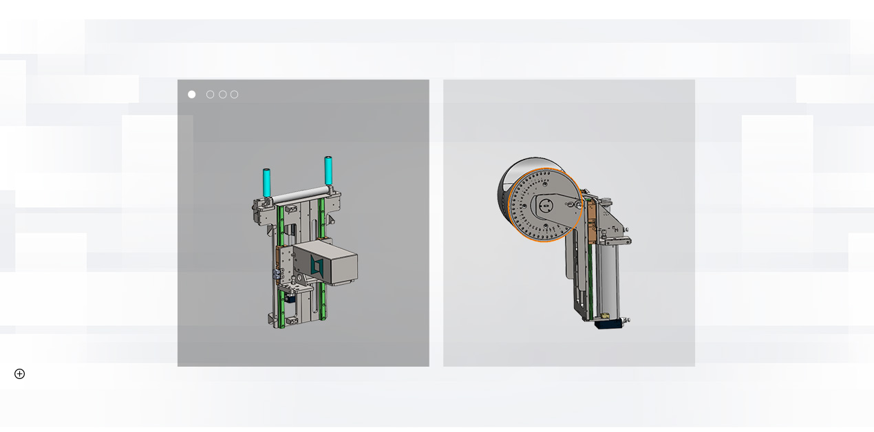
Supporting Mechanism
There are 3 sets of supporting mechanisms installed on the bed, and there are two types available:
  • Follow-up Support: Controlled by an independent servo motor to move up and down, mainly to carry out follow-up support for excessive deformation of long cut pipes (pipes with small diameters). When the rear chuck moves to the corresponding position, the auxiliary support can be lowered for avoidance.
  • Variable-Diameter Wheel Support: Lifted and lowered by the cylinder, and it can be manually adjusted to different scale positions to support pipes of different sizes.
Pneumatic Double Chuck System
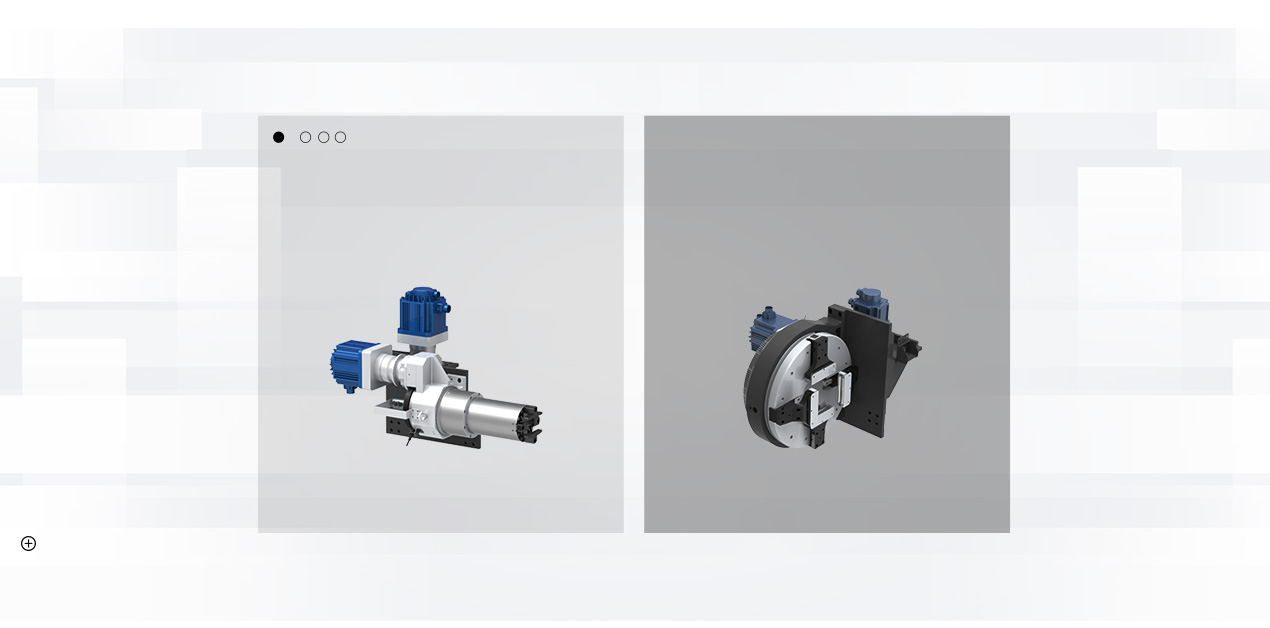
Pneumatic Chuck Left Pneumatic Chuck Right
The chuck is divided into front and rear two pneumatic full-stroke chucks, both of which can move in the Y direction. The rear chuck is responsible for clamping and feeding the pipe, and the front chuck is installed at the end of the bed for clamping materials. The front and rear chucks are respectively driven by servo motors to achieve synchronous rotation. Under the joint clamping of double chucks, short tail cutting can be realized, and the short tail of the mouth can reach 20-40mm, while supporting the short tail cutting of longer tail. The TN series pipe cutting machine adopts the method of chuck movement and avoidance, which can realize the cutting with two chucks all the time, and will not cause the pipe to be too long and unstable, and the precision is not enough.

Crossbeam and Z-axis Motion Control
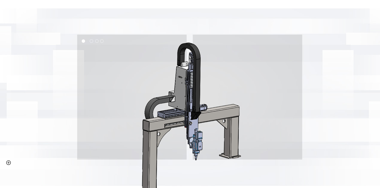
Crossbeam System Z-axis Motion Control
The crossbeam of the X-axis device adopts a gantry structure, which is welded by a combination of square tube and steel plate. The gantry component is fixed on the bed, and the X-axis is driven by a servo motor to drive the rack and pinion to realize the reciprocating motion of the slide plate in the X direction. In the process of movement, the limit switch controls the stroke to limit the position to ensure the safety of the system operation. At the same time, the X/Z axis has its own organ cover to protect the internal structure and achieve better protection and dust removal effects. The Z-axis device mainly realizes the up and down movement of the laser head. The Z-axis can be used as a CNC axis to perform its own interpolation movement, and at the same time, it can be linked with the X and Y axes, and can also be switched to follow-up control to meet the needs of different situations.
Manufacturing and Customer Support
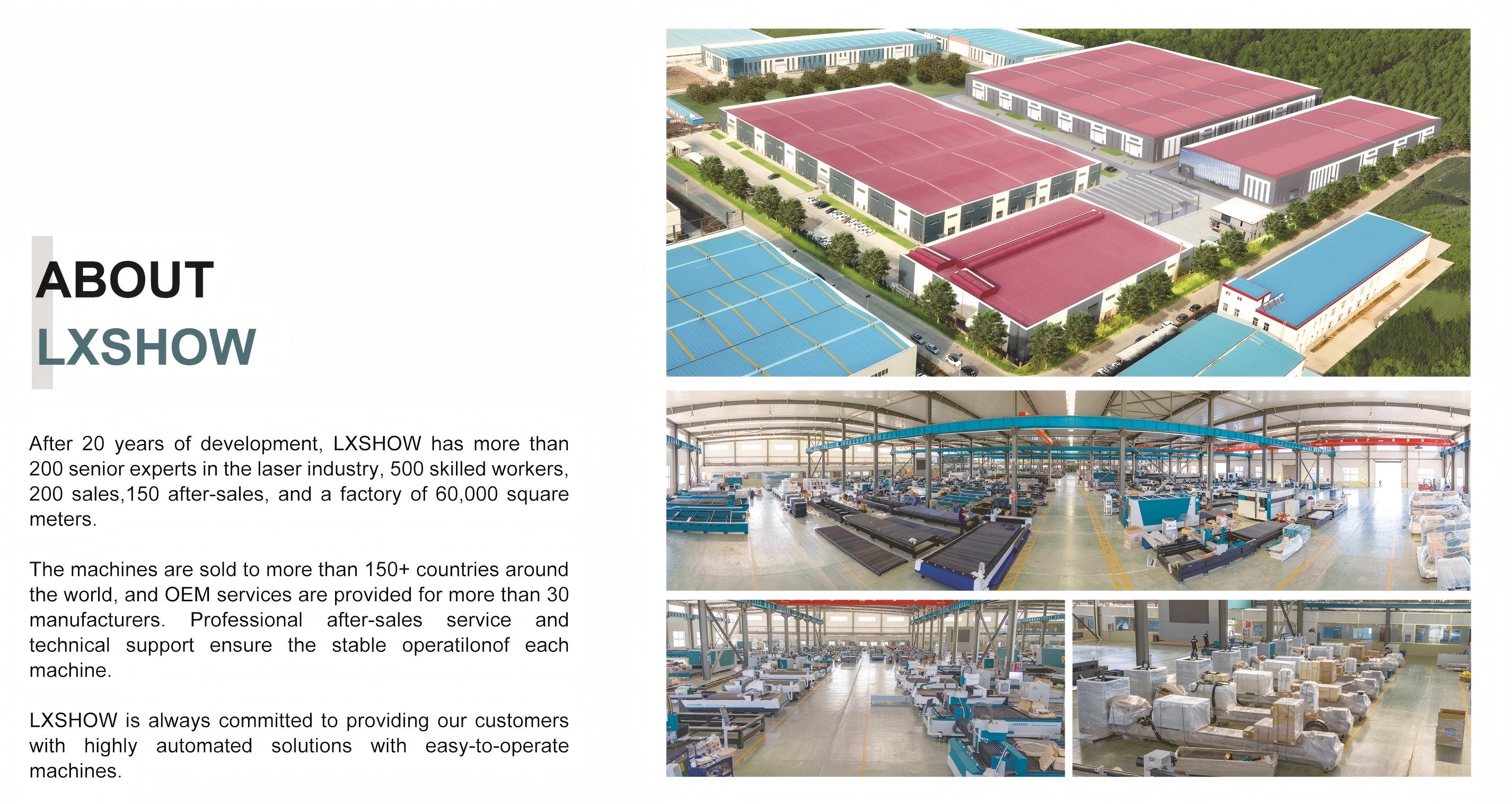
Factory
Factory Overview
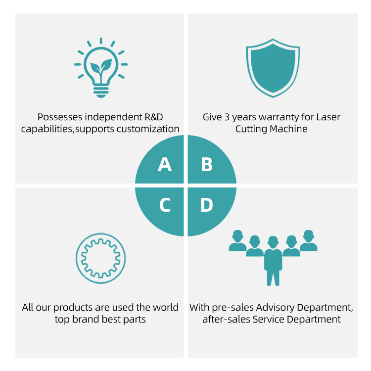
Our Service
Professional Service
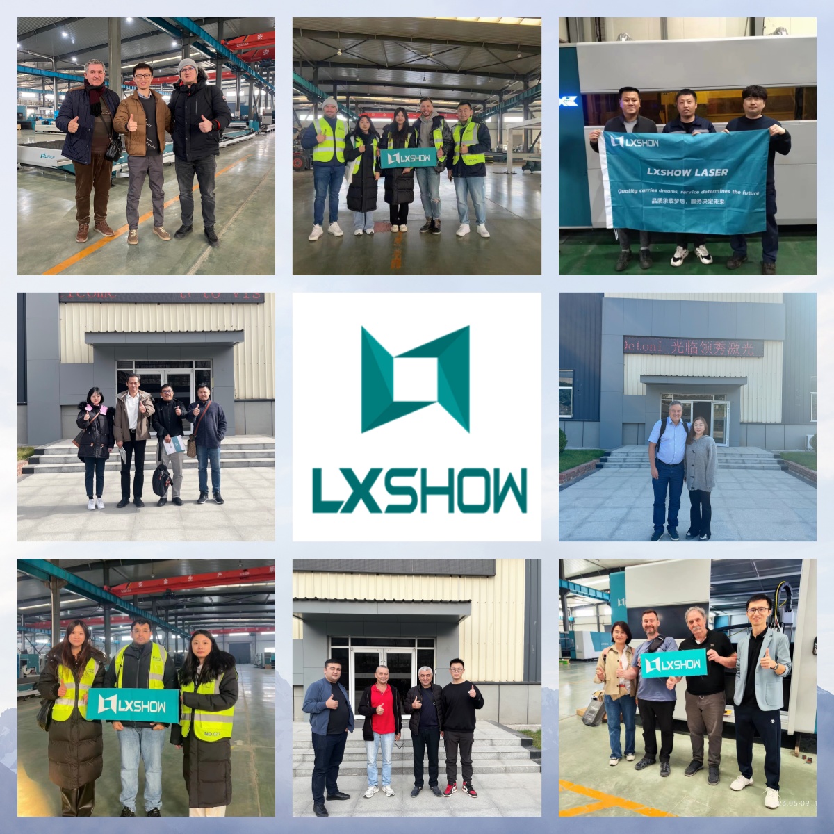
Customer Visit
Global Customer Visit
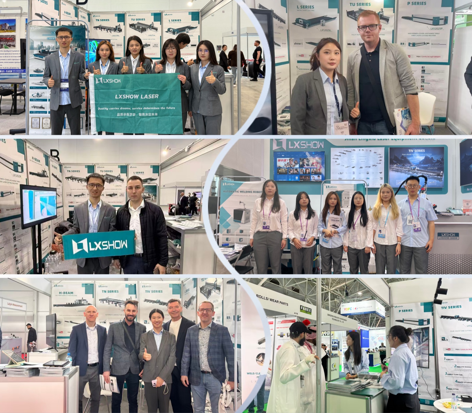
Off-line Activity
Off-line Exhibitions
Frequently Asked Questions
Do you provide CE documents and other files for customs clearance?
Yes, we provide original documentation. Initially, we will share copies with you, and after shipment, we will provide the CE certificate, Packing List, Commercial Invoice, and Sales Contract for your customs clearance process.
What are the available payment terms?
We accept multiple payment methods including TT, Western Union, Paypal, LC, Cash, and other standard payment options.
How do I learn to operate the machine after delivery?
We offer comprehensive remote support through TeamViewer, WhatsApp, Email, Phone, and Skype with camera support to guide you until all questions are fully answered.
What troubleshooting support is available if issues arise during operation?
Our technical support team is available to assist you online. Additionally, we can arrange for door-to-door on-site technical services if required.
How do I choose the correct machine model for my requirements?
To recommend the most suitable system, please provide us with your maximum work size, which allows us to select the appropriate machine bed size.
What details are needed to determine the correct laser power and industry setup?
Please provide the materials you work with and their cutting thicknesses (to determine the laser generator power), alongside your specific industry type so we can offer tailored suggestions based on our sales experience.

Related Products